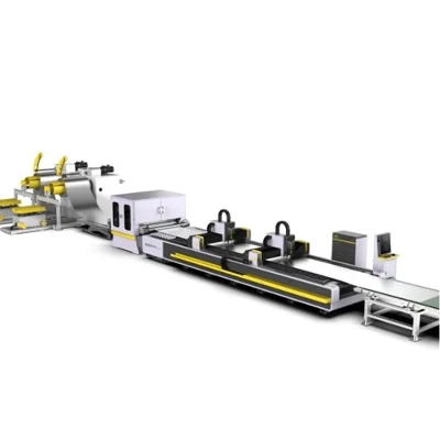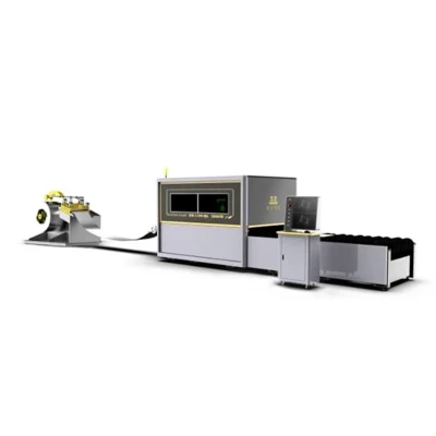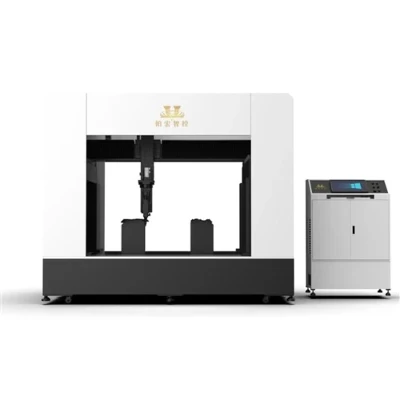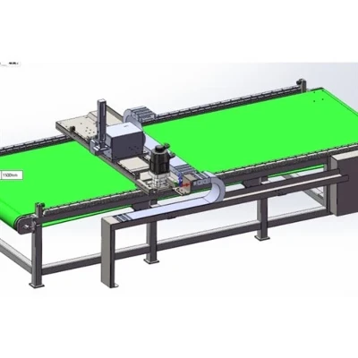


Precision Manufacturing Process for the Bed Structure
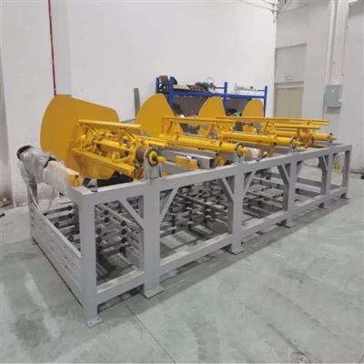
This forms the foundation for the equipment's long-term accuracy, involving six core steps designed to progressively eliminate internal stress.
Main Frame Welding: CO2 shielded welding is used to assemble the steel bed structure; welding spatter and internal defects are controlled to ensure overall rigidity.
Stress-Relief Annealing: The welded bed is placed in a 600°C annealing furnace to thoroughly eliminate residual welding stress, preventing deformation during long-term use.
Rough Machining: Excess material is rapidly removed from the raw structure, leaving a uniform allowance for subsequent precision machining.
Dual-Stage Aging Treatment: Vibratory aging is first applied to relieve internal stress, followed by natural outdoor aging for over a month to further stabilize dimensional accuracy.
Five-Sided Precision Machining: A large CNC machining center performs high-precision milling of guide rail mounting surfaces and rack mounting positions in a single setup, ensuring the parallelism and perpendicularity of all reference planes.
Guide Rail and Transmission Component Calibration:Professional technicians use dial indicators to calibrate the installation accuracy of linear guides and gear-rack systems, ensuring smooth motion without sticking and minimal backlash.
Dust-Free Assembly Process for the Optical System
Optical component assembly must be performed in an ultra-clean workshop; preventing dust contamination of the optical path throughout the process is critical, as it directly determines the quality of the laser output.
Laser Core Module Encapsulation: Processes such as splicing, coating, bonding, and cleaning of pump diodes, ytterbium-doped gain fibers, and fiber grating resonators are carried out in a dust-free environment to ensure coupling efficiency meets standards.
Dust-Free Cutting Head Assembly: Installation of collimating lenses, focusing lenses, and protective lens sets takes place inside a dust-proof enclosure; technicians wear dust-free gloves throughout, repeatedly cleaning all optical contact surfaces with isopropyl alcohol and lint-free cloths.
Fiber Connection and Alignment: The fiber connector is aligned with the positioning red dot on the QBH interface, inserted horizontally, and locked in place; upon completion, the fiber end face is inspected with a flashlight to ensure no dust particles remain. Sealing and protection: Seal the fiber optic interface and the connection point of the cutting head using gold finger tape to prevent dust from entering the optical chamber during subsequent use.